Электроника
Смотреть все
Электроснабжение и СКС
Смотреть все
Оборудование и инструмент
Смотреть все
Средства разработки электроники
Смотреть все
Телекоммуникации и связь
Смотреть все
Электронные компоненты
Смотреть все
Электромеханические компоненты
Смотреть все
Акустические компоненты
Смотреть все
Оптоэлектроника
Смотреть все
Корпусные и установочные изделия
Смотреть все
Источники питания
Смотреть все
Кабельная продукция
Смотреть все
Компенсация реактивной мощности
Смотреть все
Освещение
Смотреть все
Пожарно-охранные системы
Смотреть все
Промышленная коммутация
Смотреть все
Щитовое оборудование
Смотреть все
Электроустановочные изделия
Смотреть все
Измерительные приборы
Смотреть все
Паяльное оборудование
Смотреть все
Электроинструмент
Смотреть все
Ручной инструмент
Смотреть все
Измерительный инструмент
Смотреть все
Расходные материалы
Смотреть все
Пневмоинструмент
Смотреть все
Компьютерное оборудование
Смотреть все
Станки
Смотреть все
Оснастка для инструмента
Смотреть все
Домашняя электроника
Смотреть все
Датчики
Смотреть все
Диоды
Смотреть все
Дроссели и индуктивности
Смотреть все
Компоненты подавления ЭМП
Смотреть все
Конденсаторы
Смотреть все
Микросхемы
Смотреть все
Полупроводниковые модули
Смотреть все
Резисторы
Смотреть все
Резонаторы, генераторы и фильтры
Смотреть все
Тиристоры (триаки)
Смотреть все
Транзисторы
Смотреть все
Трансформаторы
Смотреть все
Устройства защиты, предохранители
Смотреть все
Кабельные наконечники и клеммы
Смотреть все
Клеммники
Смотреть все
Панельки и зажимы для компонентов
Смотреть все
Переключатели, кнопки
Смотреть все
Переходники
Смотреть все
Разъёмы и соединители
Смотреть все
Реле
Смотреть все
Дисплеи, индикаторы и тачскрины
Смотреть все
Светодиоды
Смотреть все
Фоточувствительные элементы
Смотреть все
Аксессуары для кабеля
Смотреть все
Лампы осветительные
Смотреть все
Вспомогательное оборудование
Смотреть все
Газовые паяльники и горелки
Смотреть все
Запчасти к паяльному оборудованию
Смотреть все
Расходные материалы для пайки
Смотреть все
Пилы, электрические ножницы
Смотреть все
Шлифмашины
Смотреть все
Абразивный инструмент
Смотреть все
Оптические приспособления
Смотреть все
Приспособления для хранения
Смотреть все
Режущий инструмент
Смотреть все
Слесарный инструмент
Смотреть все
Шарнирно-губцевый инструмент
Смотреть все
Электромонтажный инструмент
Смотреть все
Химические средства
Смотреть все


Изображение служит только для ознакомления, перед покупкой уточняйте точные характеристики в технической документации!
УТ003265593
Нет отзывов
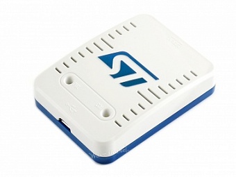
STLINK-V3SET, Модульный внутрисхемный программатор-отладчик для STM32 / STM8
STLINK-V3SET, Модульный внутрисхемный программатор-отладчик для STM32 / STM8
- Производитель: Waveshare Electronics
-
Под заказ
- Самовывоз через 6-8 недель
- Отправка возможна 4 июля
Минимальный заказ от 1 шт
Кратность заказа
1 шт
8 738,20 ₽
Доставка курьером по Москве (в пределах МКАД)
Ориентировочная стоимость (Время доставки и итоговая стоимость согласуются индивидуально с каждым клиентом):
Товар весом до 10 кг - 500 ₽
Товар весом свыше 10 кг - 800 ₽
Доставка в любой регион РФ почтой России и транспортными компаниями: СДЭК, 5POST, Boxberry, Деловые линии, DPD.
Стоимость доставки зависит от города назначения и размера посылки. Вы можете самостоятельно рассчитать стоимость доставки на сайтах транспортных компаний.
Самовывоз по адресу г. Москва Варшавское ш., д.26, стр. 10
Выдача товара производится согласно графика работы:
Пн-Чт: с 9:00 до 18:00
Пт: с 9:00 до 17:00
Обед с 13:00 до 14:00 - выдача товара не производится.
Оплата только безналичным способом!
Мы не работаем с наличным расчетом
Мы не работаем с наличным расчетом
Вы можете оплатить заказ следующими способами:
- Онлайн оплата банковской картой (Visa, MasterCard, МИР, Union Pay) через процессинговый центр ПАО «Сбербанк».
- Через систему быстрых платежей (СБП) по QR-коду.
- Через агрегаторов платежных систем Ю-касса или LifePay.
- В личном кабинете «Сбербанк Онлайн» в разделе «Переводы и платежи», «Перевод организации».
- Лично в отделении банка при предъявлении распечатанного счета.
STLINK-V3SET, modular in-circuit debugger and programmer for STM32/STM8
Description
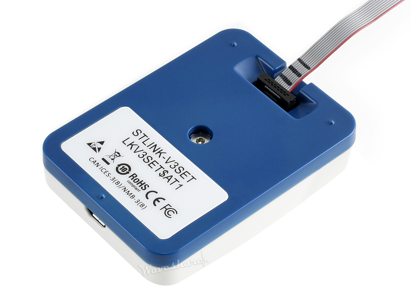
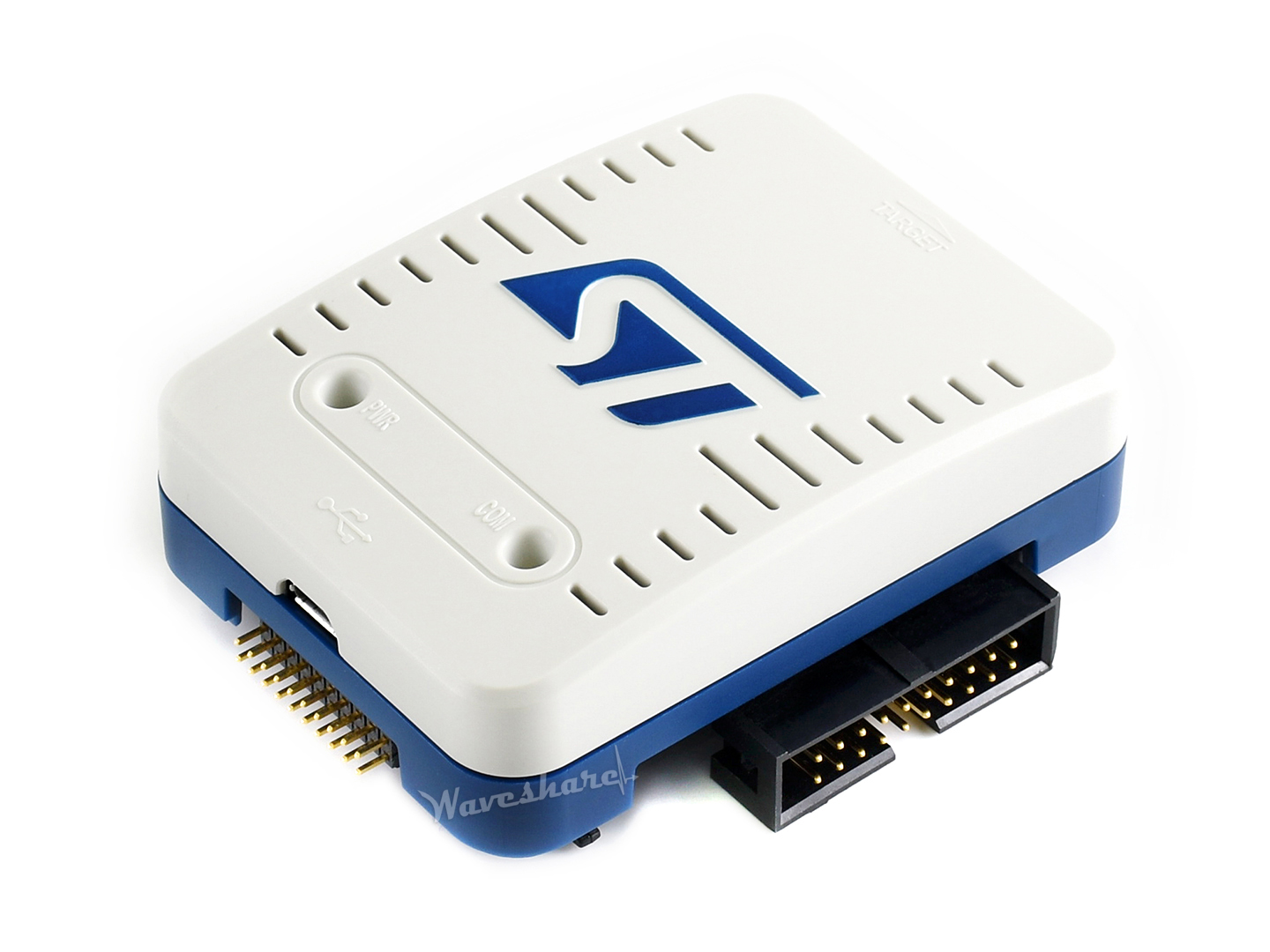
The STLINK-V3SET is a modular stand-alone debugging and programming probe for the STM8 and STM32 microcontrollers. It is composed of a main module and a complementary adapter board.
The SWIM and JTAG/SWD interfaces are used to communicate with any STM8 or STM32 microcontroller located on an application board.
The STLINK-V3SET also provides a Virtual COM port interface allowing the host PC to communicate with the target microcontroller through one UART, and bridge interfaces (SPI, I2C, CAN, GPIOs) allowing for instance the programming of the target through bootloader.
The modular architecture of STLINK-V3SET enables to extend its main features through additional modules such as the adapter board.
Key Features
- Stand-alone probe with modular extensions
- Self-powered through a Micro-B USB connector (does not provide power supply to the target application)
- USB 2.0 high-speed compatible interface
- Direct firmware update (DFU) support, to use with more future devices
- JTAG / serial wire debugging (SWD) specific features:
- 3 V to 3.6 V application voltage support and 5 V tolerant inputs
- Flat cables STDC14 to MIPI10 / STDC14 / MIPI20 (connectors with 1.27 mm pitch)
- Flat cable for 20-pin JTAG/SWD (2.54 mm pitch) (extra free cable from Waveshare)
- SWD and serial wire viewer (SWV) communication support
- SWIM specific features (only available with adapter board MB1440):
- 1.65 V to 5.5 V application voltage support
- SWIM header (2.54 mm pitch)
- SWIM cables with dual 4-pin connectors / 4-pin connector to separated pins (2.54 mm pitch) (extra free cables from Waveshare)
- SWIM low-speed and high-speed modes support
- Virtual COM port (VCP) specific features:
- 3 V to 3.6 V application voltage support on the UART interface and 5 V tolerant inputs
- VCP frequency up to 15 MHz
- Available on STDC14 debug connector (not available on MIPI10)
- Multi-path bridge USB to SPI/UART/I2C/CAN/GPIOs specific features:
- 3 V to 3.6 V application voltage support and 5 V tolerant inputs
- Signals available on adapter board only (MB1440)
- Drag-and-drop Flash programming
- Two color LEDs: communication, power
Supported Software
- STM32CubeProgrammer
- KEIL RVMDK
- IAR EWARM
- GCC-based IDEs
Supported Devices
- All STM8 MCUs with SWIM interface
- All STM32 MCUs with JTAG / SWD interface
Specification Comparison among Different STLINK Versions
| Comparison | STLINK-V3SET | STLINK-V3MINI | ST-LINK/V2 | Remarks |
|---|---|---|---|---|
| JTAG/SWD application voltage | 3V - 3.6V | 3V - 3.6V | 1.65V - 3.6V | ST-LINK/V2 supports STM32 low-power devices |
| SWIM application voltage | 1.65V - 5.5V | N/A | 1.65V - 5.5V | STLINK-V3MINI doesn't support SWIM of STM8 |
| SWV support | YES | YES | YES | only available for STM32 at present |
| Debug interface | multi | multi | 2 | STLINK-V3SET/MINI feature GPIO port besides the programming port |
| LED indicator | two colors | two colors | two colors | two colors LED indicates both power and communication, while red color LED indicates only communication |
Connect to PC
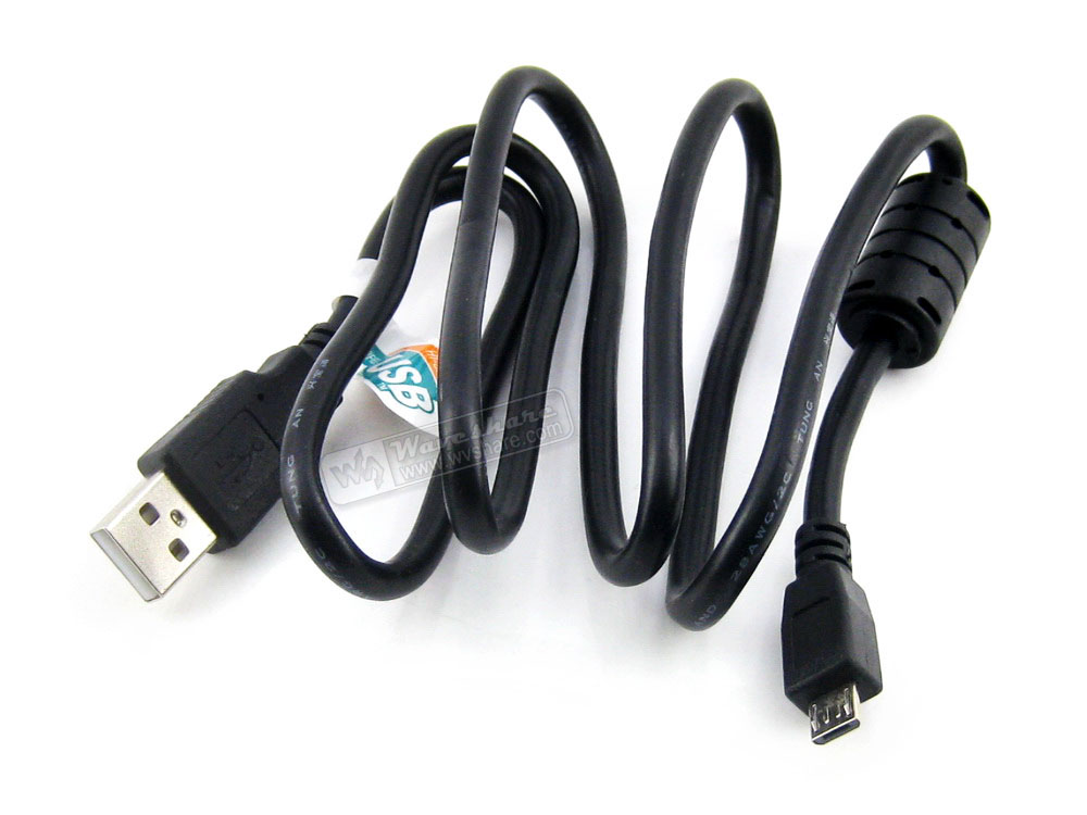
The STLINK-V3SET should be connected to the PC via a USB Micro-B cable.
- Before connecting, install/update the IDE/STM32CubeProgrammer to support the STLINK-V3SET (drivers)
- STLINK-V3SET adopts an STM32 F7 microcontroller, supports USB2.0 high speed communication
Connect to STM32 applications
The STLINK-V3SET can be connected to STM32 target applications on JTAG / SWD interfaces, which are available on both the main module (MB1441) and the adapter (MB1440).
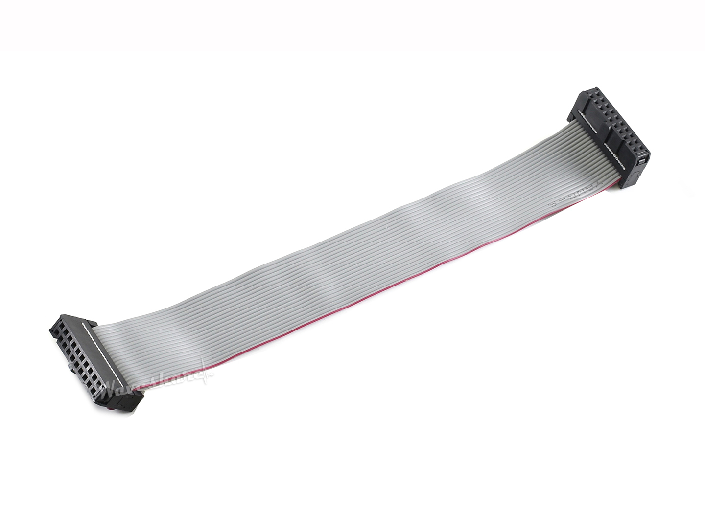
- Three official STDC14 flat cables, plus an extra free legacy 20-pin flat cable, are delivered. Choose the proper one to use.
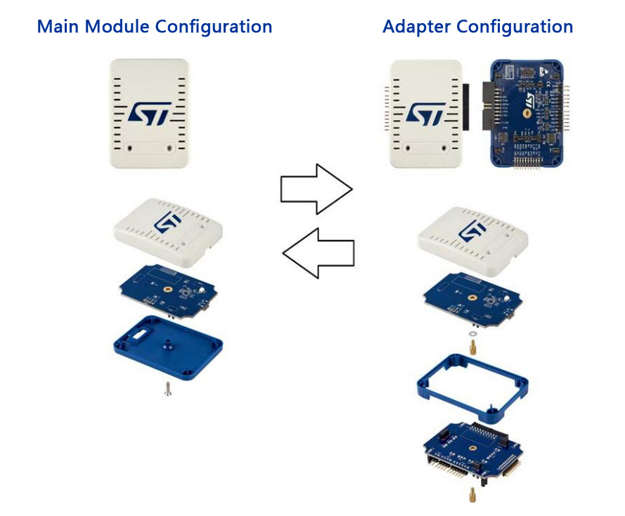 Figure 1. Assemble the STLINK-V3SET in different configuration
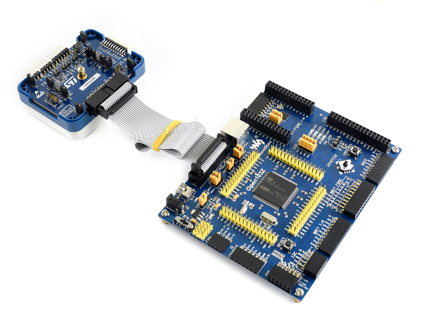 Figure 2. Connect to STM32 application on 20-pin JTAG / SWD connector
Connect to STM8 applications
The STLINK-V3SET can be connected to STM8 target applications on SWIM interface, which is only available on the adapter (MB1440).
- JP4 and JP6 on the MB1440 board must be ON in order to activate the SWIM protocol
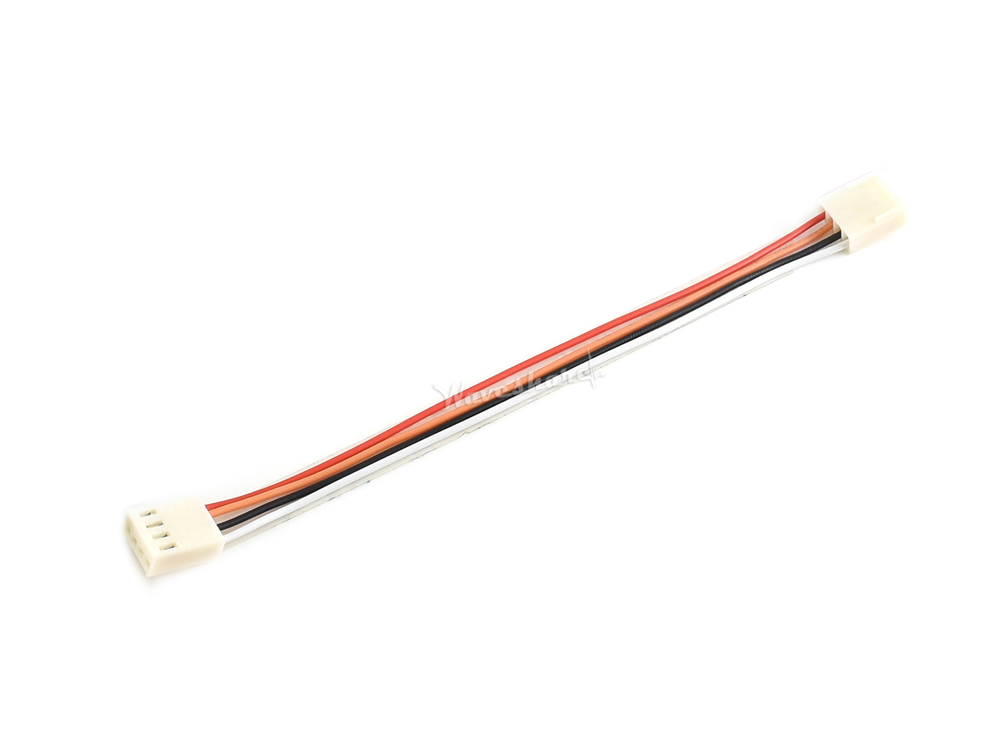
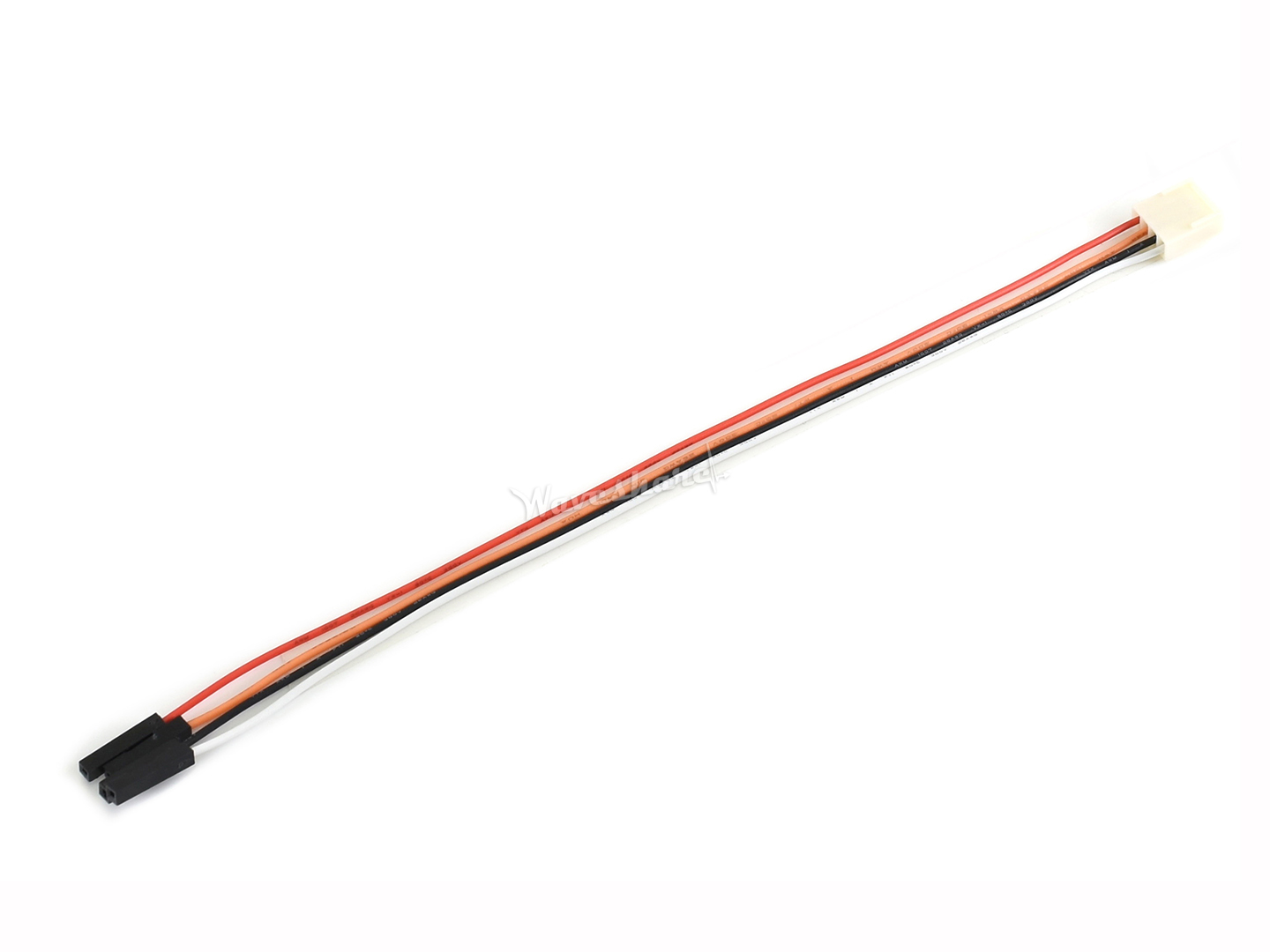
- We also provide two extra free SWIM cables for easy use
- Make sure the pin-to-pin mapping is correct, especially the VCC and GND, to avoid damaging the STLINK-V3SET
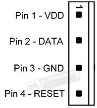 Figure 3. SWIM header pinout
 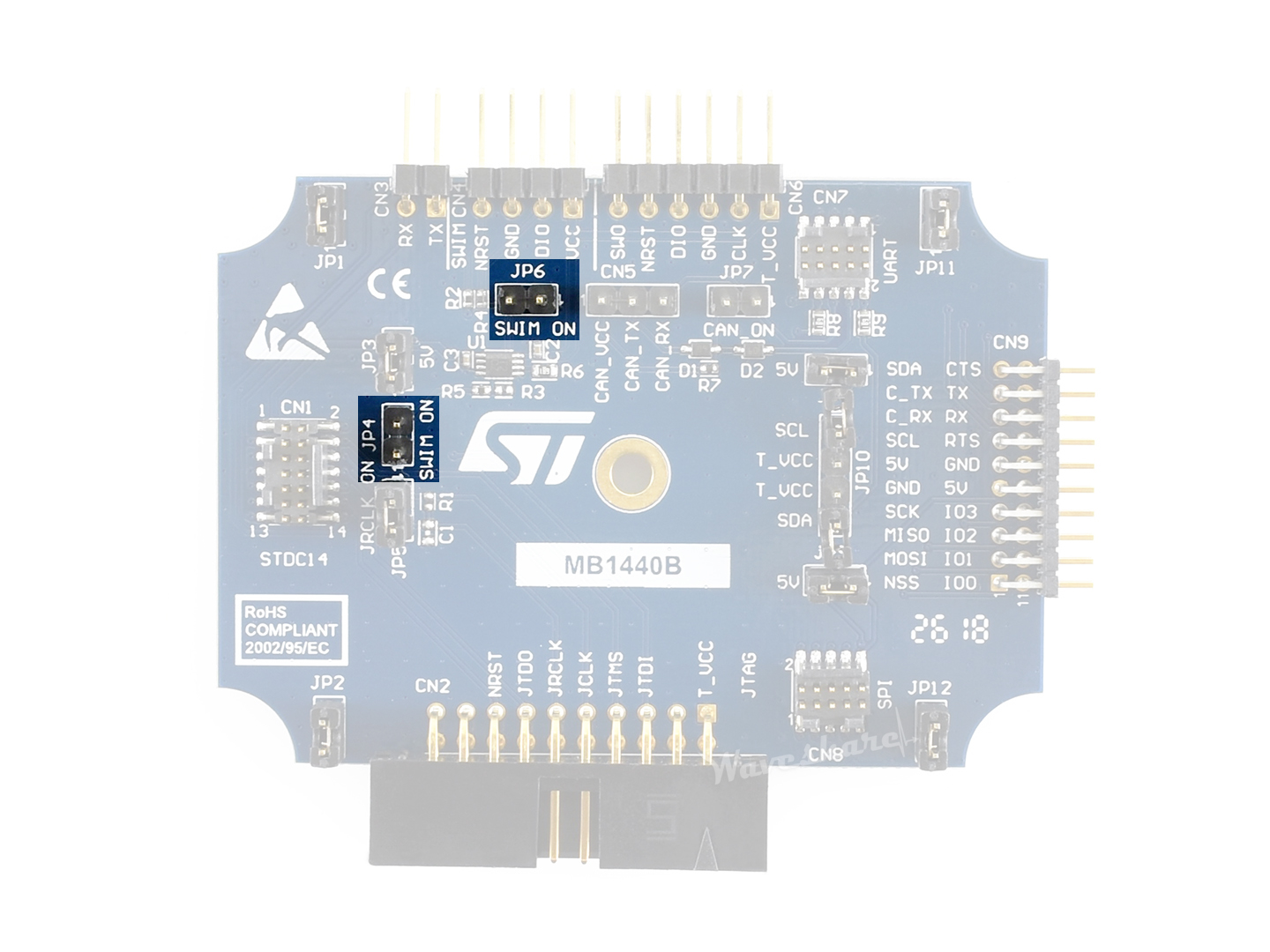 Figure 4. JP4 and JP6 must be ON
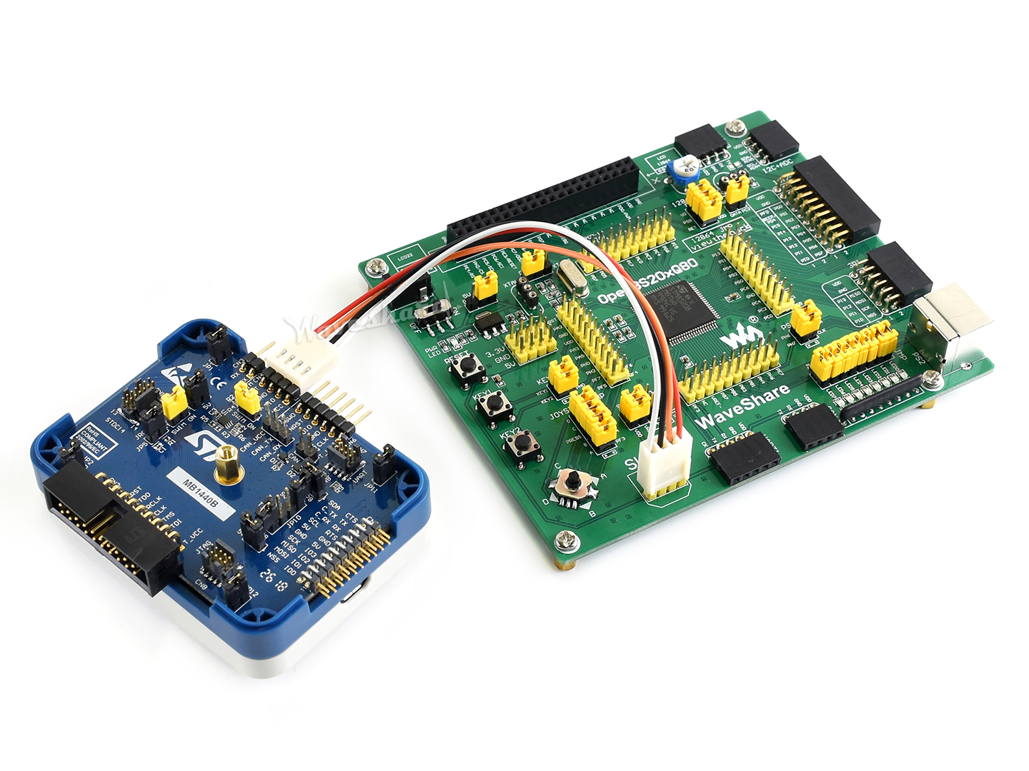 Figure 5. Connect to STM8 application
STLINK-V3SET LED Status
- COM LED is blinking RED: the first USB enumeration with the PC is taking place.
- COM LED is RED: communication between STLINK-V3SET and the PC is established (end of enumeration).
- COM LED is blinking GREEN/RED: data are being exchanged between the target and the PC.
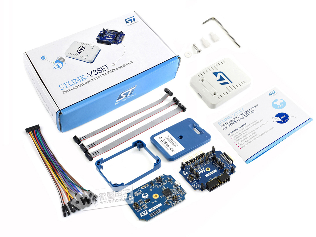
Комплект поставки
- STLINK-V3SET x1
- USB type A plug to micro B plug cable x1
- 20-pin JTAG/SWD flat ribbon (extra free) x1
- SWIM dual 4-pin connectors cable (extra free) x1
- SWIM 4-pin connector to separated pins cable (extra free) x1
1
2
3
4
5
Бренд
Производитель
ST Microelectronics
Основная группа
Внутрисхемные программаторы, эмуляторы, отладчики
Нет отзывов
Популярные товары
Хит
Доставка в течение 1 дня
Хит
Товар дня

Доставка в течение 1 дня
Хит

Доставка в течение 1 дня
Хит
Распродажа
Доставка в течение 1 дня